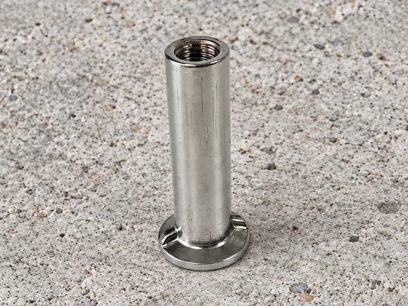
Round-Base Cast-In Ferrules
Round-body cast-in ferrule forms with an enlarged base and internal thread. Define the foot profile, body length and threaded interface on your drawing.
View product →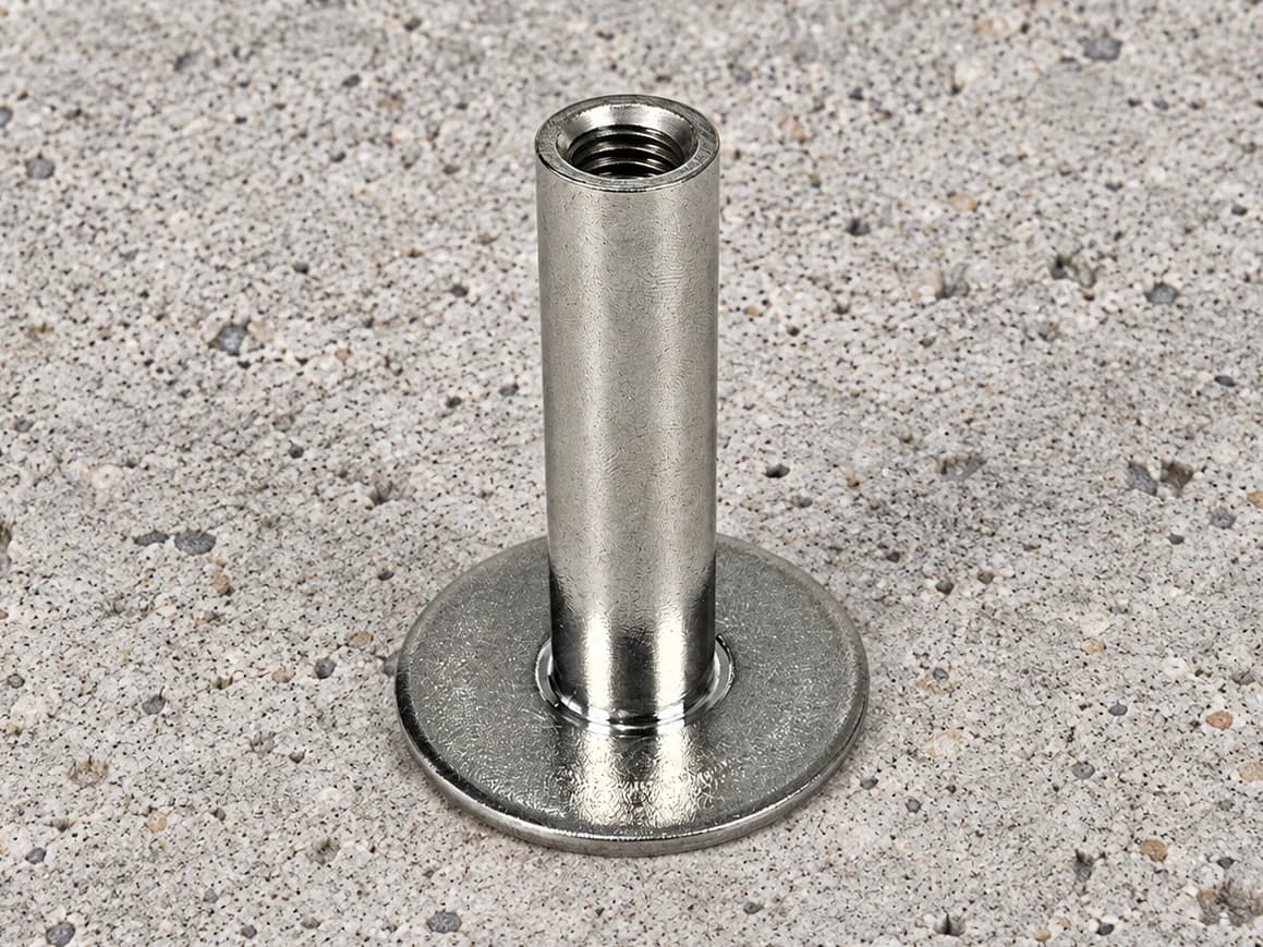
Swipe to explore the product views.
Internally threaded sockets with a circular plate base. Define the plate diameter, socket position and thread details for a drawing-based inquiry.
Share your drawing, material specification and quantity.
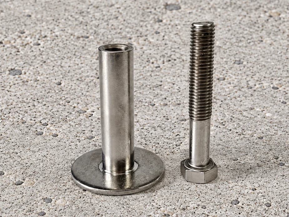
Round plate lifting socket components feature a cylindrical socket above a circular base plate. Their identifying feature is the separate, flat circular footprint around the socket. This distinguishes the illustrated assembly from square plate anchors and from ferrules with a compact shaped foot.
Specify plate outside diameter and thickness, the required socket position, and any edge or flatness requirements relevant to the assembly. The socket drawing should define overall height, bore and internal thread details. If concentric positioning is required, give an explicit datum and tolerance rather than relying on the appearance of a centred photograph.
A circular plate may be selected in a project drawing because of the available component footprint. This is a geometry choice, not evidence that the component has a lower embedment requirement, a greater capacity or an interchangeable installation detail compared with a square plate design.
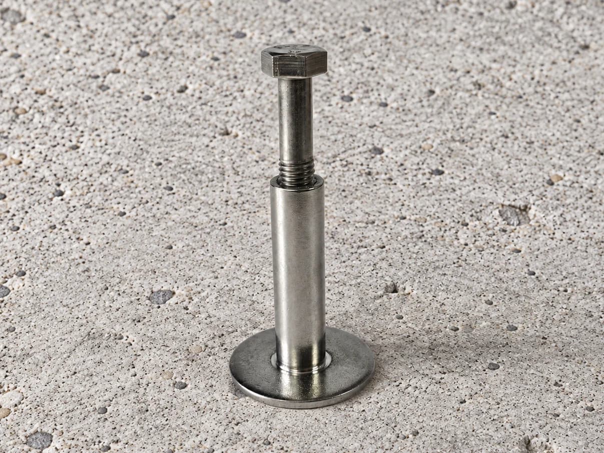
The supplied images include both an open socket and a bolt fitted into the socket. Clarify which components are to be supplied, how the plate and socket are joined, and whether the mating fastener is a separate procurement item.
For lifting-related projects, supply the approved component drawing and required verification scope. Concrete conditions, reinforcement, thread compatibility and the complete lifting arrangement must be addressed in the project documents; no lifting rating is assigned by this product description.
Tolerances, order quantity and lead time are assessed for the project.
Send your drawing →The illustrated product has a distinct flat circular plate beneath the socket. A compact flanged foot is a different geometry and should not be treated as the same component without a drawing comparison.
Submit the required diameter, thickness and socket position for manufacturing review. Acceptance and any dimensional limits are assessed for the actual drawing.
Not on thread size alone. Substitution requires review of the complete geometry, joining details and project design requirements.
Share your drawing and requirements. Let’s discuss the manufacturing route.
Compare other component forms for your drawing requirements.
Round-body cast-in ferrule forms with an enlarged base and internal thread. Define the foot profile, body length and threaded interface on your drawing.
View product →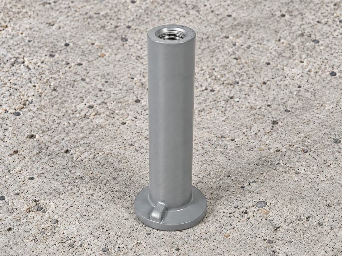
Threaded precast insert forms with a cylindrical body and ribbed circular flange. Match the geometry and finished interface to your project drawing.
View product →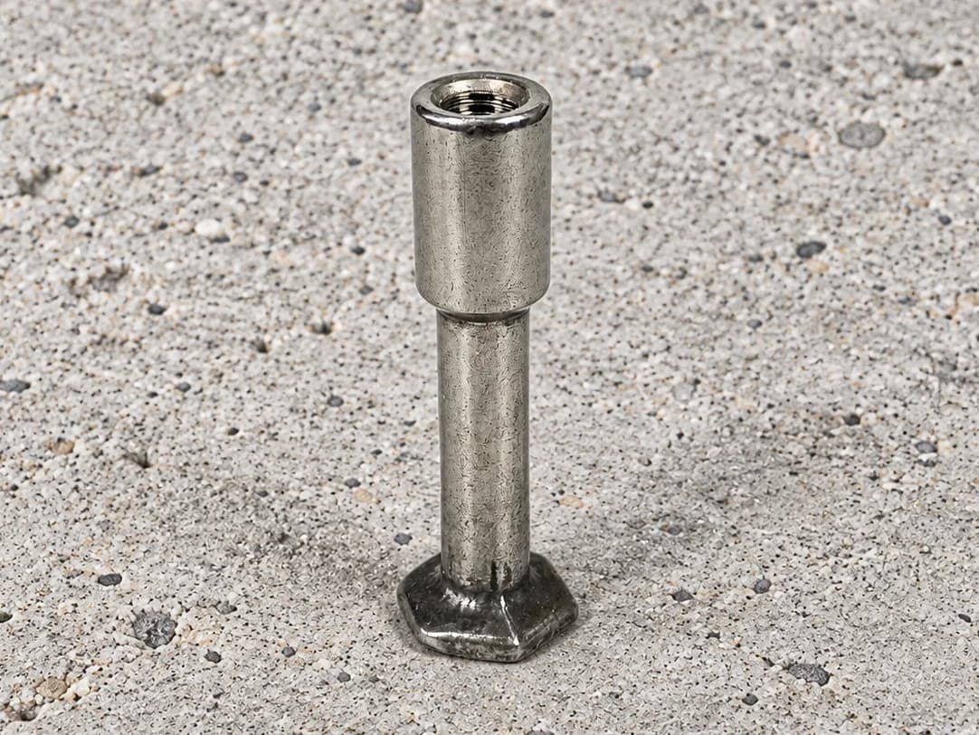
Foot anchor components with an enlarged threaded head, reduced shank and polygonal foot. Specify each section and the complete assembly requirements.
View product →